1. Process Positioning and Operational Value
Within the PCB (Printed Circuit Board) manufacturing ecosystem, the Dry Film Process represents the "soul of pattern transfer." This critical operation directly determines trace precision, layer-to-layer alignment, and the ultimate electrical performance of the final product. From an operational perspective, the dry film process serves as the essential transformation hub connecting engineering design (EDA data) to physical reality; any yield fluctuation here exponentially impacts manufacturing costs across subsequent lamination, drilling, and plating operations.
The dry film process primarily covers two major application scenarios: inner layer circuit fabrication (for multilayer boards) and outer layer patterning. Compared to wet film (liquid photoresist) processes, dry film offers advantages including consistent film thickness, higher resolution (capable of 40μm line/space), environmentally friendly operation, and suitability for High-Density Interconnect (HDI) applications. Although material costs per unit are higher, dry film remains the irreplaceable standard process in high-end consumer electronics, automotive electronics, and server board manufacturing segments.
2. Complete Process Flow and Control Points
2.1 Pre-treatment: The Foundation of Adhesion
Process Principle: Through mechanical grinding or chemical micro-etching, copper oxide layers are removed and surface roughness increased to enhance mechanical bonding between the dry film and copper foil.
Operational Control Priorities:
-
Surface Roughness Control: Ra values typically maintained at 0.3-0.6μm; excessive roughness causes line width variation, while insufficient roughness leads to adhesion failure and film lifting.
-
Chemical Cleaning Solution Concentration: Copper ion concentration in micro-etching solutions (such as SPS systems) requires real-time monitoring, with recommended inspection once per shift.
-
Water Rinse and Drying: Absolutely essential to ensure no water stains remain on the board surface, as residual moisture causes bubbles during lamination, resulting in exposure defects.
Equipment Configuration: Horizontal pre-treatment machines (incorporating acid cleaning → micro-etching → recycled water rinse → DI water rinse → hot air drying sections). Operationally, pay close attention to conveyor roller cleanliness to prevent copper powder back-contamination on board surfaces.
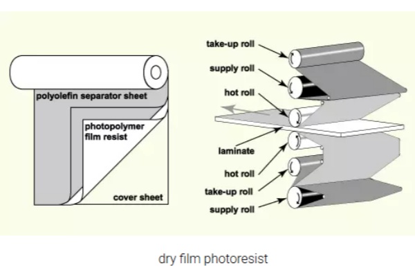
2.2 Lamination: Prerequisite for Defect-Free Transfer
Process Principle: In a vacuum or quasi-vacuum environment, heated rollers (typically set at 105-115°C) laminate the three-layer dry film structure (PET carrier film + photoresist layer + PE protective film "sandwich") onto the copper surface. Upon heating, the photosensitive resin in the resist layer softens and flows, filling microscopic copper surface irregularities, then forms uniform coverage upon cooling.
Critical Process Parameter Operations Matrix:
| Parameter Dimension |
Standard Range |
Out-of-Control Risk |
Monitoring Frequency |
| Lamination Temperature |
105-115°C |
Too low → poor adhesion; Too high → solvent evaporation, reduced photosensitivity |
Measure every 2 hours |
| Lamination Speed |
1.5-3.0 m/min |
Too fast → bubbles; Too slow → thermal damage |
First-article confirmation |
| Roller Pressure |
0.4-0.8 MPa |
Uneven → film thickness variation |
Daily inspection |
Operating Environment Control: Dry film is sensitive to ultraviolet light, requiring Yellow Room conditions with illumination controlled below 10-30 Lux. Operationally, establish strict material buffer management mechanisms; laminated boards must cool for at least 15 minutes before stacking to prevent residual heat from causing film layer adhesion.
2.3 Exposure: Where Pattern Precision is Determined
Process Principle: Using phototools (film masks) as light-blocking media, UV light (365-410nm wavelength) triggers photochemical reactions in the dry film. For negative-working films, exposed areas undergo photopolymerization (cross-linking/curing) while unexposed areas remain soluble; positive-working films behave conversely.
Core Operational Actions:
Phototool Management
-
Dimensional Stability Control: Sensitive to temperature and humidity, with thermal expansion coefficient ≤1.5×10⁻⁵/℃; storage maintained at 21±2℃ with 50-60% humidity.
-
Phototool Lifespan: Typically limited to 3000-5000 exposures, with mandatory retirement at limit.
-
First-Article Confirmation: Each batch requires dimensional stability measurement (typically ≤1.5mil) to confirm phototool-to-substrate matching.
Exposure Machine Operation Standardization
-
Vacuum Alignment: Vacuum level ≥650mmHg ensures no gaps between phototool and board, preventing halation.
-
CCD Automatic Alignment: Captures panel edge targets and phototool targets for sub-pixel alignment, with accuracy required within ±15μm.
-
Exposure Energy Control: Monitored using Stouffer 21-step exposure scales, requiring 6-9 steps covered, corresponding to 50-120mJ/cm² (adjusted for specific dry film models).
Common Abnormality Operational Responses:
-
Alignment Shift: Establish "Three No's" rule—no board rotation, no mid-process phototool adjustment, no visual estimation.
-
Ghosting: Caused by insufficient phototool opacity or vacuum failure; requires regular phototool surface cleaning and Mylar film integrity checks.
2.4 Developing: The Critical Pattern Revelation Step
Process Principle: Using weak alkaline developer (typically 1-3% sodium carbonate solution, Na₂CO₃), soluble dry film (unexposed for negative film, or exposed for positive film) is dissolved, leaving the desired circuit pattern. The chemical reaction: R-COOH + Na₂CO₃ → R-COO⁻Na⁺ + NaHCO₃.
Horizontal DES (Develop-Etch-Strip) Line Operational Parameters:
| Item |
Process Window |
Abnormality Impact |
| Developer Concentration |
0.8-1.2% |
Too low → incomplete development; Too high → excessive side-etching |
| Temperature Control |
28-32℃ |
Temperature variation affects dissolution rate consistency |
| Spray Pressure |
20-30 psi |
Too high → trace damage; Too low → residue |
| Conveyor Speed |
3.5-4.2 m/min |
Must match developer activity |
Quality Control Checkpoints:
Break Point Monitoring: Ideally controlled at 40-60% of developer tank length, maintained by adjusting speed or concentration.
Rinse Cleanliness: Recommend three-stage counter-flow rinsing, with final exit board resistivity ≥5MΩ·cm to prevent sodium carbonate crystallization contamination.
First-Article Optical Inspection: Use 40x magnification to confirm no sawtooth edges, no scum residue, and line widths within tolerance (typically ±10%).
2.5 Subsequent Related Processes (Etching and Stripping)
While strictly speaking subsequent operations, these require operational coordination with the dry film process:
Inner Layer Etching
Uses acidic cupric chloride etchant (CuCl₂/HCl system), requiring etching factor ≥3.0 to ensure controllable line width loss.
Key metrics: Undercut controlled within 10μm, etching uniformity ≥90%.
Stripping
Uses 3-5% sodium hydroxide (NaOH) solution at 50-55℃ to dissolve cured dry film.
Operational risk: Incomplete stripping causes uneven black oxide/browning, affecting lamination bonding strength.
3. Operational Efficiency and Yield Improvement Strategies
3.1 Intelligent Upgrade Pathways
Pre-Lamination AOI Deployment: Immediately following development, deploy AOI equipment using CAM comparison algorithms to automatically detect opens, shorts, nicks, and protrusions, enabling immediate rework and preventing defects from entering lamination where waste would be significantly higher.
3.2 Digital Process Control (SPC)
Establish real-time SPC monitoring for exposure energy, break points, and line width CPK:
- CPK≥1.67: Excellent process capability, maintain current status.
- 1.33≤CPK<1.67: Enhanced monitoring required, identify variation sources.
- CPK<1.33: Immediate production halt for investigation of equipment or material abnormalities.
3.3 Green Manufacturing and Cost Optimization
Developer Regeneration Systems: Employ ion exchange or electrodialysis technology to recover sodium carbonate, reducing chemical consumption by 30-40% while decreasing wastewater COD discharge.
Dry Film Scrap Management: Establish strict First-In-First-Out (FIFO) protocols; opened dry film must be used within 48 hours to prevent moisture absorption and performance degradation.
4. Conclusion
As the core pattern transfer technology in PCB manufacturing, the dry film process's operational refinement directly determines a company's process capability and profitability. From copper surface preparation before lamination, to precision alignment during exposure, to chemical control in development, every step requires strict Standard Operating Procedures (SOPs) and inspection mechanisms. Driven by high-end application demands including 5G and AI chip packaging substrates, dry film processing is evolving toward finer line/space (below L/S 30/30μm), larger panel sizes (up to 24×28 inches), and higher layer counts (20+ layer MLB). These trends impose higher requirements on operational teams' process control capabilities. Only by organically integrating equipment automation, process digitalization, and quality systematization can manufacturing advantages be maintained in intense market competition.


 IPv6 network supported